• MEC 120 Project 3

    Hardware Organizer for Robotics Class

    As my 3rd project I chose to help a member of the faculty address a problem his students were facing in the robotics class. I was asked to design a hardware organizer for hardware and other parts. The final product would be assigned to each student to allow them to keep loose hardware contained. Since a full product development cycle went beyond the scope of this project I have chosen to end it after analyzing the first prototype.
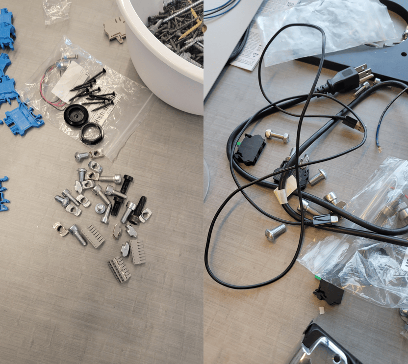
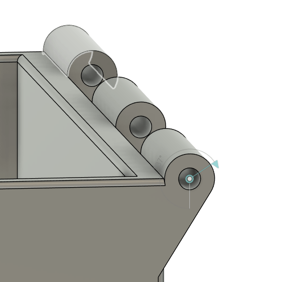
    I began my project with several constraints in mind. I knew that the final product would need to fit on the print bed of one of the machines in Protoworks. Trey asked that the compartments be large enough to fit M8x48 bolts. We also decided to test the idea of using printer filament as a hinge pin.
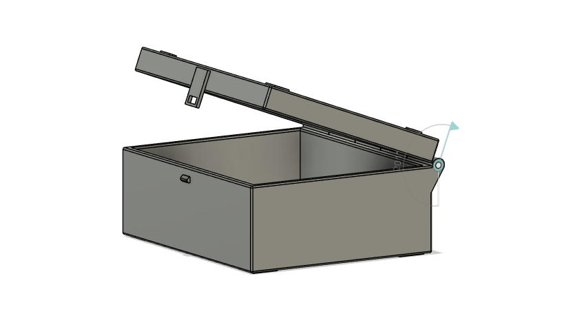
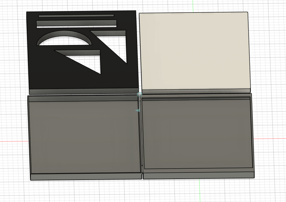
    As Project 2 also involved making a box I was able to apply the lessons learned and make a more complex model in far less time. I made use of the point project tool to allow my sketches to align to my model.

    I also made use of mirror and offset face tools to allow my design tolerances to be edited on the fly.
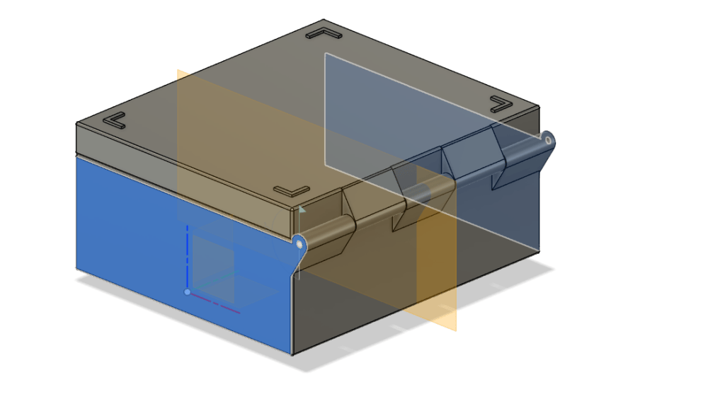
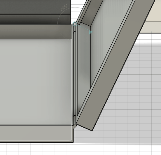
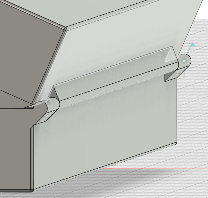
    I chose to make my first model be much smaller than the final product. I decided the most complicated portion of the design would be the filament hinge, so I decided to solve that problem before scaling the size of the design.
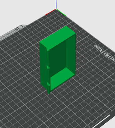
    I sliced and printed my prototype on the Bambu Lab P2S using a PLA filament.
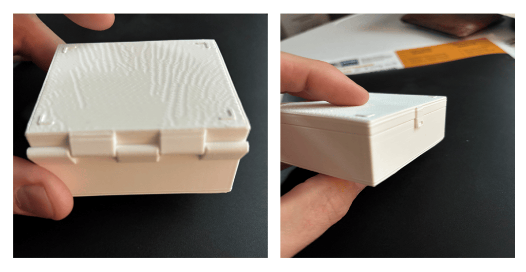
    While my box looks cool it will need a lot of finishing before it can be used to test a filament hinge. I was able to draw a number of conclusions from the prototype:

    1. Hinges will not retain shape if printed in flat position.

    2. Wall thickness of hinge barrels will need to be increased.

    3. Use bigger filament for pin

    4. Print in vertical orientation instead.

    5. Tolerances between moving components are too tight.

    6. Hinge barrels may need to be finished by drilling to size.

    7. Stack enabling feet need to be reworked.

    8. Vertical print might allow for print in place hinge
    Since I have satisfied the requirements for assignment I am going to table this design. I may well pick it up again as I think it is highly likely I will be given a product development project before too much longer.

    I think that using CCAC Protoworks to make a product to help another department is a cool idea. My concern is that it will be difficult to produce large orders in a space which is set up for research and development. The limited number of matching printers creates a bottleneck which would significantly lengthen the production time.
  • MEC 120 Project 2

    A Box for Sketch Tools.

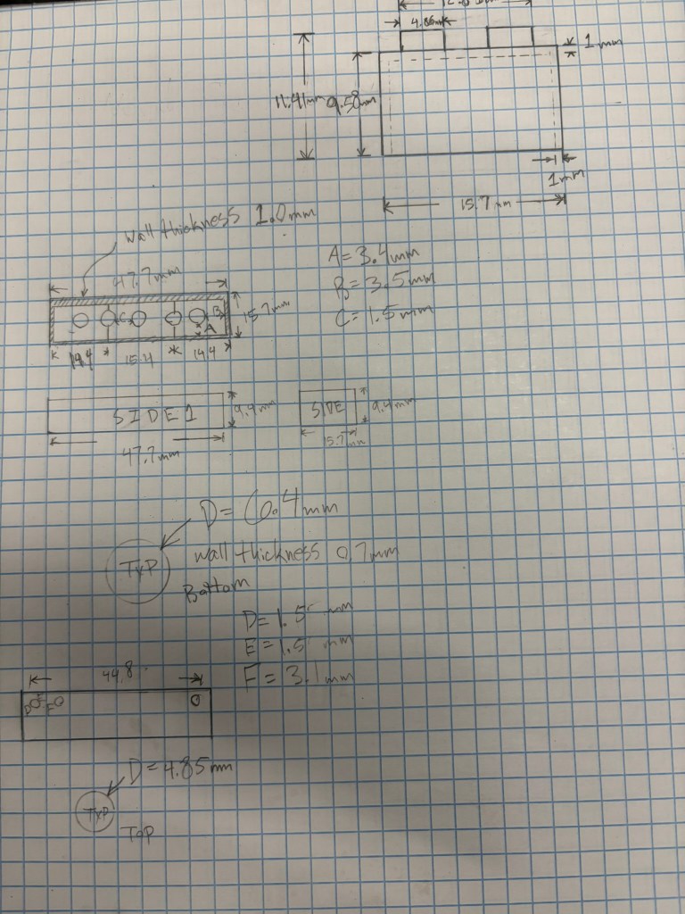
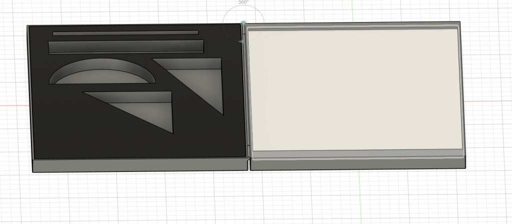
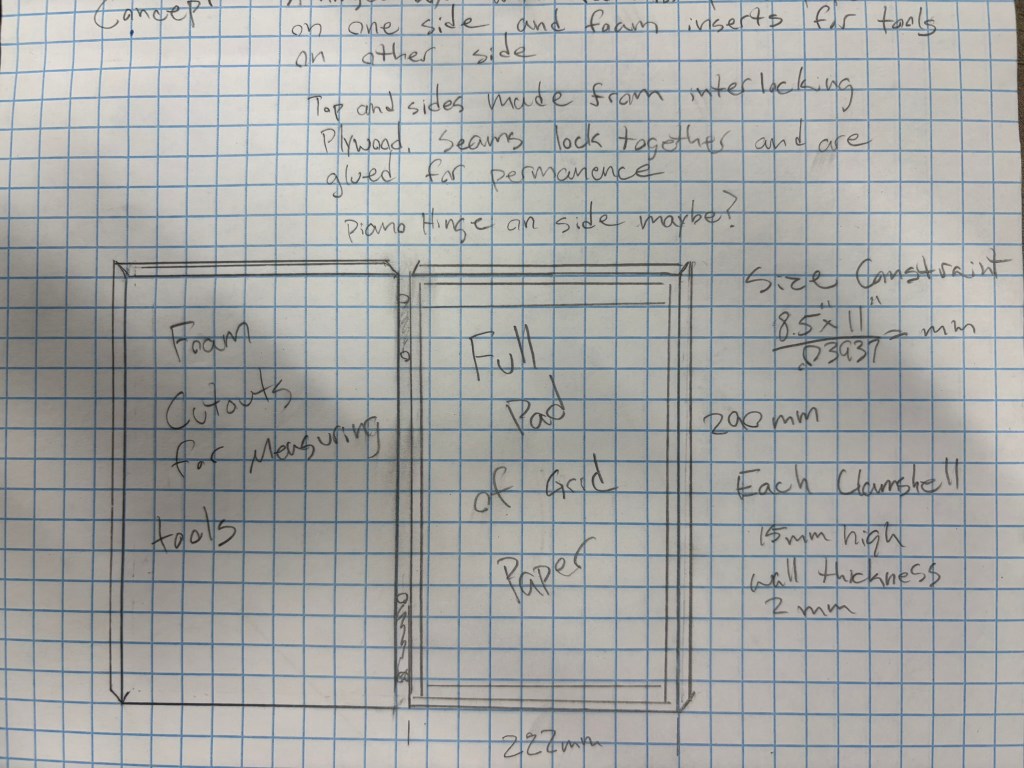
    I chose to design a box which contained everything needed to do basic concept sketches. I wanted to have paper on one side and strait edges and other marking tools on the other.

    I set the size of the box to be just slightly larger than an 8.5x 11 pad of paper. I wanted it to be easy to load a new pad, but not loose enough for the paper to be able to move around.

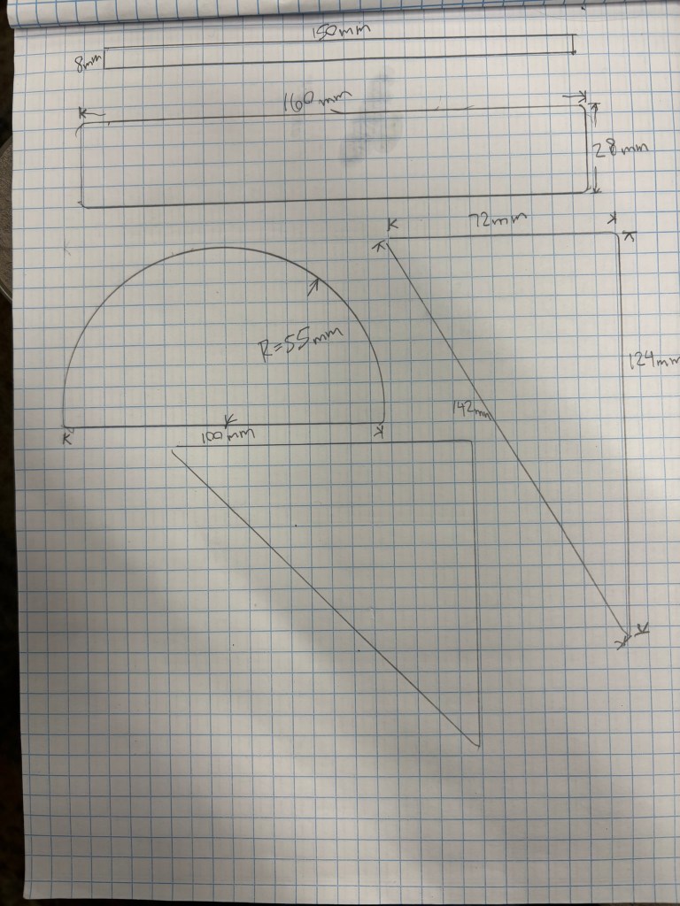
    I took measurements for my straight edges and pens in order to create foam inserts to hold them.

    I modeled a basic box in Fusion. I made sure there was a way to prevent paper from falling out of the right side of the box.

    I next created a basic hinge and added an axis of rotation in order to allow the box to open and close.

    My biggest takeaways from this project was the importance of a good workflow in order to allow modifications further along in the process. I also learned a lot about how to manipulate components and add movement and constraints.

    If

  • Logo Project

    Goal: to create a logo for my portfolio website.

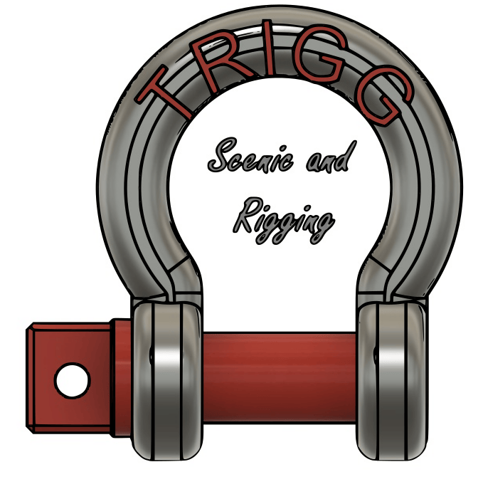
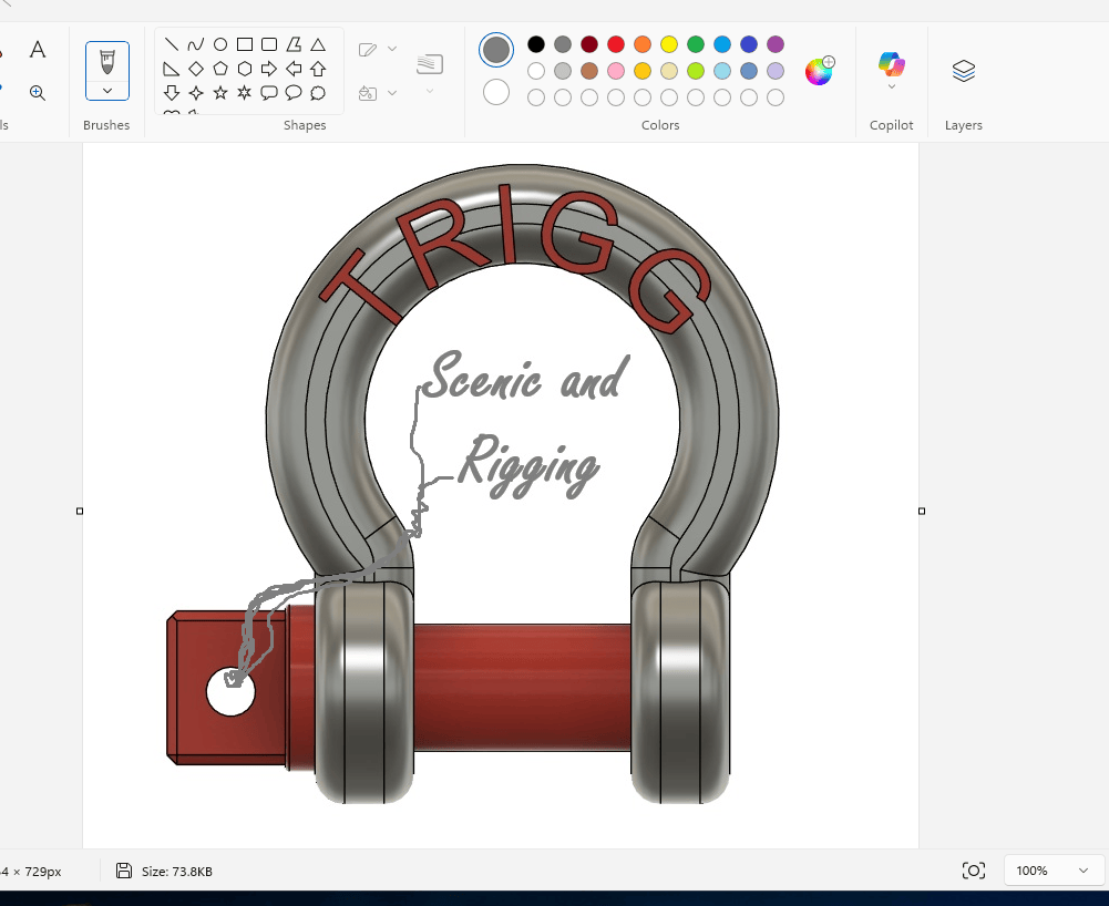
    My primary goal for this site is to have a place to present my school work. I also want to show off some of the work i have done in my career as a rigger and fabricator. I chose to build my logo around a shackle because it is one of the most integral pieces of rigging equipment.

    I started by making a 3D model of a shackle in Fusion.

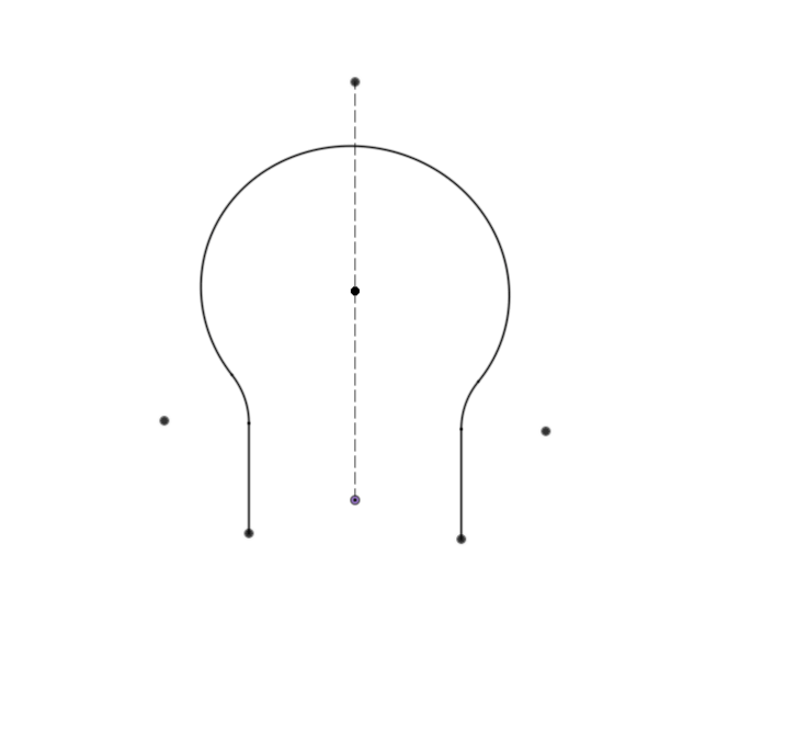
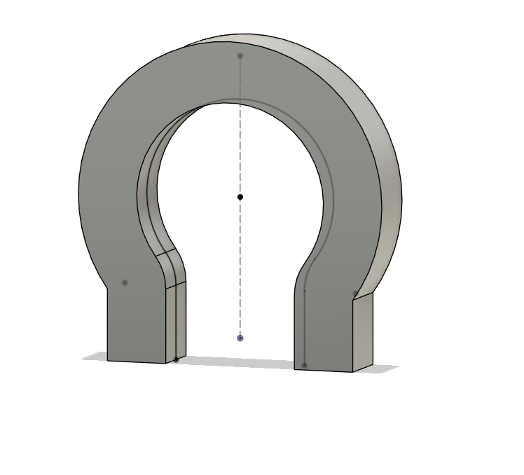
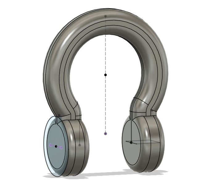
    I created a couple of construction planes and drew a sweep path in order to extrude the basic shape of the shackle bell.

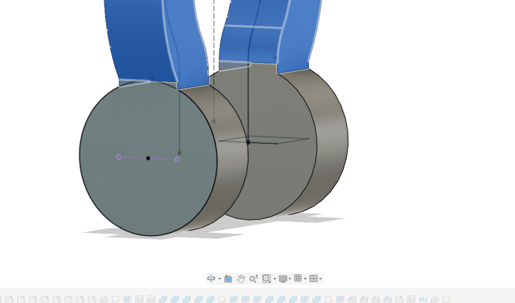
    I then projected points from the sweep path sketch and used them to create a new sketch from which to extrude the ears.

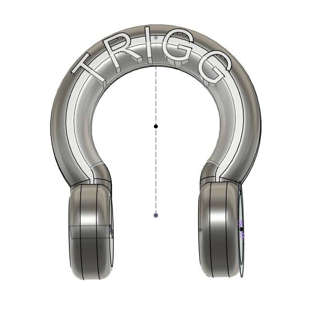
    From there it was a matter of trying different fillet values in order to get the correct look for the part. I then added the text along the sweep path before extruding my name. I wanted the text to appear as though it was part of the bell, so I extruded it from the midplane and changed its place in the design timeline until I got the correct look.

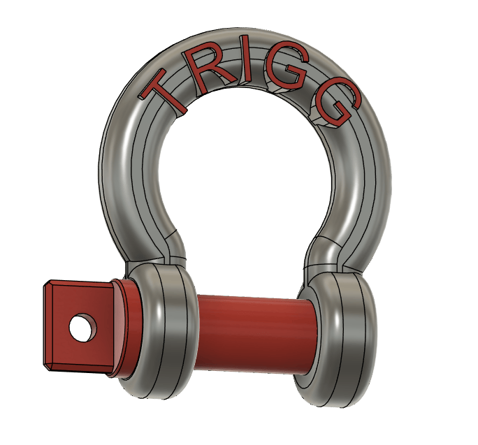
    I finished the model by adding a shouldered screw pin and finding the correct color.

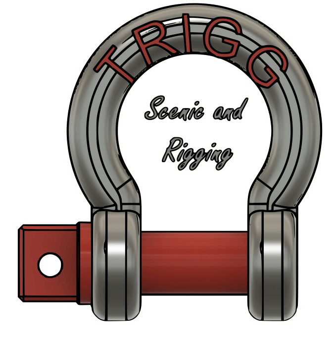
    I took a screen shot of my shackle over to inkscape in order to add the center text and convert the image to .svg

    I think my logo turned out pretty well. By building it in Fusion i was able to play with the structure of the shackle until i had the correct proportions.

    I also had the idea to add mousing wire and use the ends of the wire to spell the center text.

    Here is a concept sketch I made using microsoft paint. I will continue working on this as I find the time.

  • MEC 120 Project 1

    Assignment: Create sketches of a Lego brick. Make a model in Fusion then slice and print. Compare finished brick to the real thing.

    Measuring and sketching went well. We were handicapped by the quality of the calipers, but given the scope of the assignment this was not a big issue.

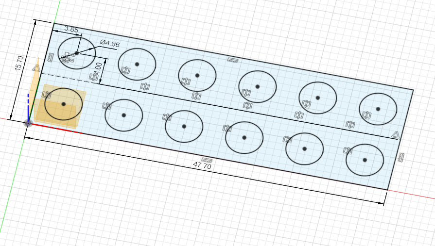
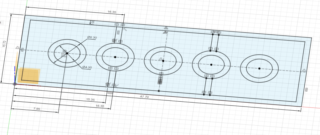
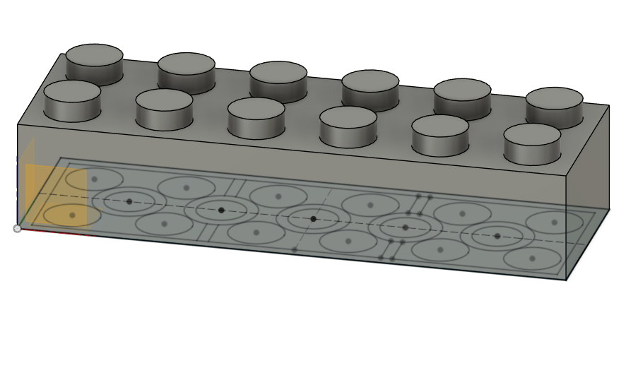
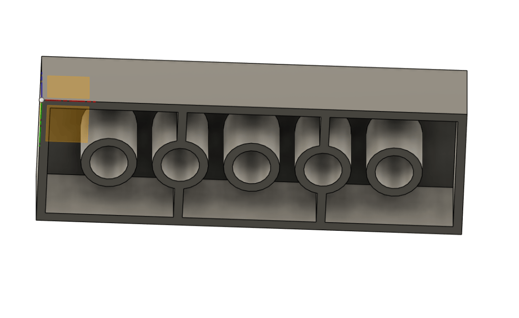
    My fusion model consisted of 2 sketches, one of the inner cylinders and one of the studs on the top of the brick.

    I used the offset extrude tool for the sketch of the studs to make sure the resulting bodies were located in the correct places. Once all bodies were created I was able to combine them into one contiguous brick.

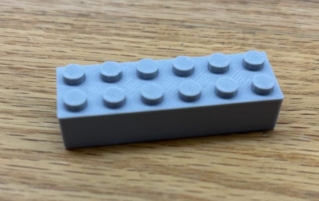
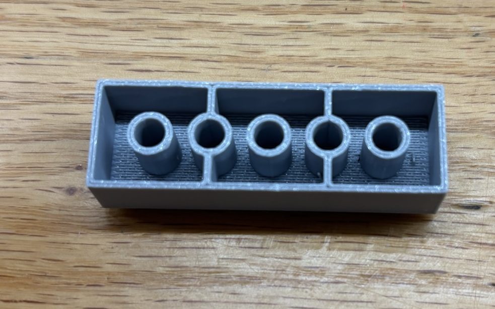
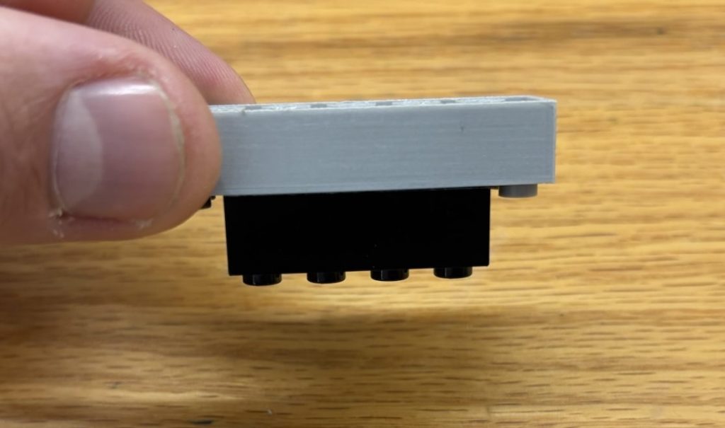
    The final printed part is very similar to an actual Lego brick. The top studs are sized well enough to allow them to bond with the bottom of a LEGO brick, but my sizing of the interior cylinders did now allow my brick to snap to a LEGO brick in the same way.

    Final Thoughts: I thought the assignment went well. If I were to try it again I would start by using better calipers. I would also upsize my internal cylinders enough to allow them to generate some friction with the studs on the top face of another brick. This last step may take a lot of experimentation.